|

All
information presented
on this website is
presented 'as is',
with no warranty,
suitability,
or fitness
of purpose implied.
I do not accept any
responsibility for any injury
resulting from use
or misuse
of this information.
Your
use of this information
constitutes acceptance
of these terms. |
I
made an Axworthy flying bicycle-wheel ghost last year and it needs
to be upgraded. I have chosen to start with the ghost itself.
A new head, body, and extended arms, all the while lightening
up the character as compared to the original. It will have looser
joints, a wig form head, more sculpted body and different frock.
In
other words, last years version was not as cool as it can be.
I think everyone gets caught up in the mechanics, so I want to
touch on the aesthetics.
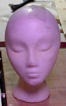
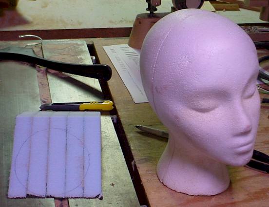
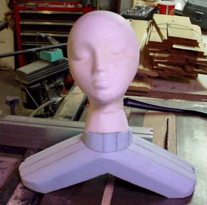
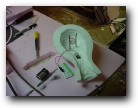
The
materials are pretty basic. A wigform, some dense polyfoam board,
some stiff wire, and scrim. Liquid Nails will hold most of it
together (note that I started using PolyUrethane Glue (PUG) as
it holds the foam so much better than liquid nails). So the whole
thing to this point will cost maybe 10 bucks. Start with a wigform
like shown.
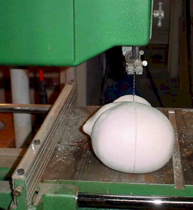
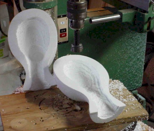
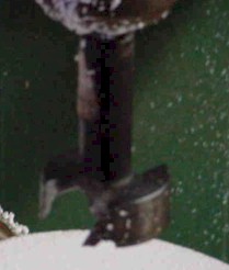
I took the head, and sliced it in half. I wanted it lighter, so
I hollowed it out a bit using a forstner bit on my drill press.
Make sure not to thin it out to much, since it gets whipped around
pretty much on the cable when rounding bends.
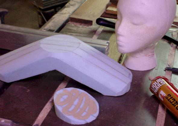
Next, I will need a body, really just shoulders and arms to attach
this to. Take a piece of the hi-density foam, and cut a strip
about 5-6" tall (this is the 1" thick stuff) and then
trace a hanger, preferably a heavy duty suit style hanger, onto
1 end of the foam strip.
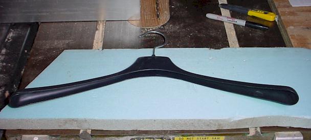
This will give you a basic form, and length the strip needs to
be. Cut off at the end of the tracing, and then make 5-6 pieces
from the strip the same length. Glue them together face to face
to make a stack, with the tracing on the outside. Let the liquid
nails dry.
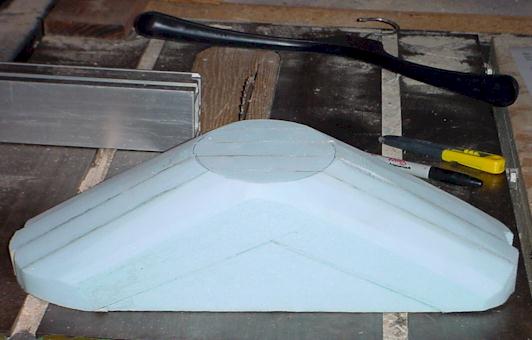
Now measure down about 1.5" from the top of each shoulder
and draw a line on the foam. Where the llines meet near the apex
and hits the ends of the stack will be the outline of the shoulders.
Now cut the top excess off the stack to get the rough pyramid
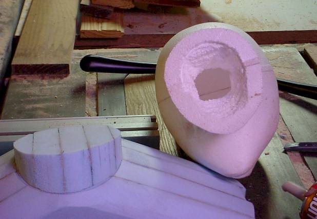
form, and lay it on the side. Measure the width of the neck on
the wigform, and draw a line across the stack face that wide,
below the apex. Cut off excess above that line to give you the
neck base. Place the stack so that the neck stump is facing up,
and place the wigform on top of that flat area. Trace the neck
onto that flat. This will give you a outline to sculpt the foam
to for a more natural looking set of shoulders. Personally, I
used the combo sander to grind away all the excess rounding out
the shoulders and getting a nice taper around the neck outline.
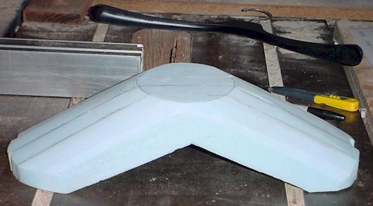
At this point, you can cut out the excess below the shoulders
(you drew those lines earlier) to lighten it up more. We just
left it there before to make the whole thing rigid while shaping
it, now that its shaped, the excess is unneccesary.
I think the prop would look better with the head slightly tilted
back, since it will be floating around overhead. This will give
it the appearance it is flying towards the ToTers as opposed to
just flying around. To do this, I took the wedge that was cut
out from beneath the shoulders, and traced the neck of the wigform
on to it.
Now that gets cut out.

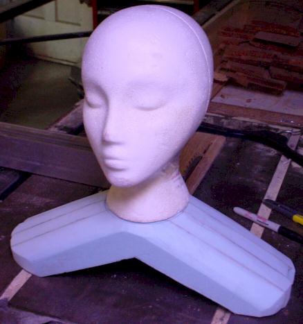
And
glued into place on the shoulders with some liquid nails.
Before I glue this together, I ground the base of the wigform
neck down a bit to make a better transition to the neck stump.
Then you need to glue the wigform to the neck stump, but only
the front half gets glued since I will be putting a battery with
leds to make the eyes glow inside the wigform hollow, and a connector
(a fishing swivel with leader hook) to connect the whole assembly
when completed to the guide line with.
|
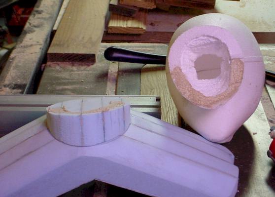
After it all dries together, I will contour where the neck base
of the wigform meets the neckstump so the transition is better.
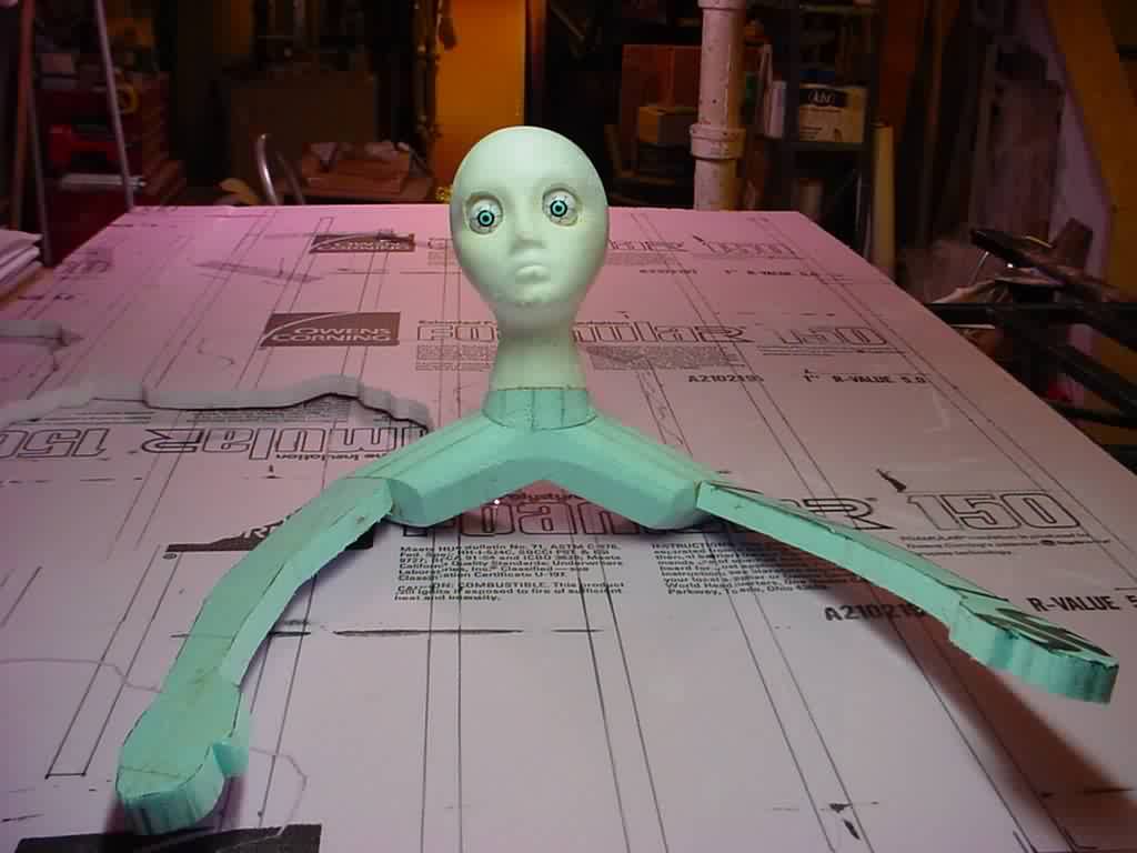
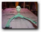
Next I seperated the head sections, and added some traced out
and formed foam arms using shishkeebob skewers and PUG to hold
them in position, just slightly askew. Simply
traced my own arms tilting the marker in under my arms to get a
thin outline, cut them out with a razor knife, and glued them in
place. The arms are not
equal in size or angle as relative to the shoulders, and this
causes a slight amount of wobble as the BWG travels on its lead.
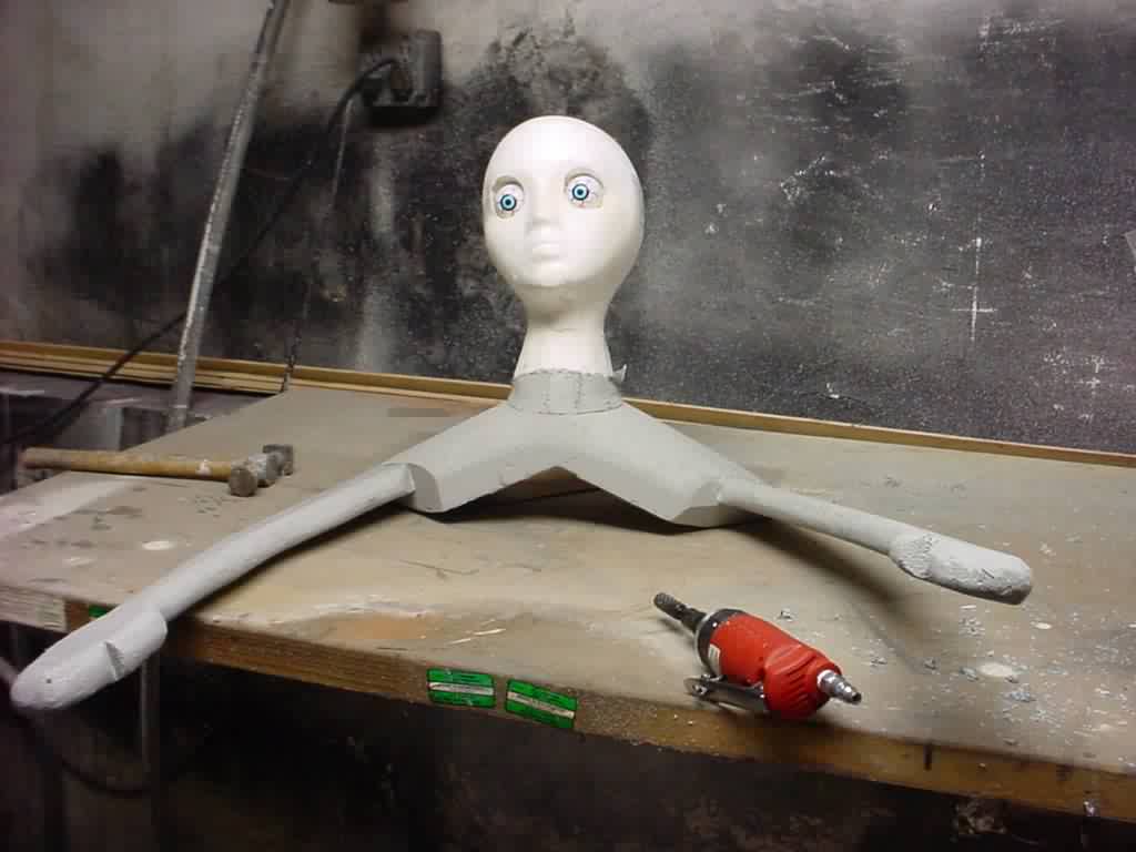
Once the glue is set, I use a dair
driven die grinder and a course bit to soften the lines of the
arms rounding them over a bit so the fabric to be placed on the
figure drapes nicely without a crisp crease.
With the arms formed and
attached, it is time to move on to the head, and the glowing eyes.
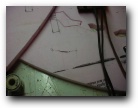
First, find the centerline of the eyes on the wigform and
draw a line to the back side of the rear half of the wigform,
This gives you a reference line to align the posts that will support
the LEDS. Following that, I added some posts to suport the LEDS
stuck into the foam and afixed with a dab of PUG. While I am working
on this part, I figured it was time to add a hanging loop from
some heavy gage copper motor winding wire I had on hand, so I
tried to find a reasonable balance point on the figure (to keep
it from being to head heavy and leaning forward too much). Next
since this was to run only at night, and it has a battery to power
the LEDs (this is running on a loop course, so it would be very
difficult to provide a plug in power source) and I wanted to be
able to switch them on and off. I drilled a hole for a single
pole single throw toggle switch on the base of the wighead where
it meets the top of the neck, passed the switch thru the hole
added a dab of glue, and afixed it with the retainer nut. Next
a 9v battery connector was soldered to one of the switch contacts.
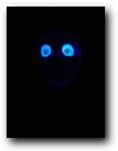
Then the LEDs were soldered in series, seeing that these are
UV LEDS with 4 volt draw, I figured between the cold and the hours
of usage, I was pretty safe not using a resistor, and was correct.
These UV LEDS are pretty tuff.
Not being the electronics wiz, Todd Snyder put together a
little tutorial on how to calculate for what size resistor is
needed in this excepted email from the Halloween-L
list serve:
"Each LED requires 4 volts across it to light up.
If you want to light up more LED's you string them together (but
current only flows through them in one direction so you have to
string them up in series). Dont worry, if ones hooked up backward,
it blocks all current and nothing will happen.
Total voltage
has to equal 4 X (number of LEd's).
What you say
you only have a 9 volt wal wart to power these. Well, then your
gonna need a resister in-line to limit the current. (NOTE:if you
only had a 6 volt walwart two LED's would never light)
Now its more
complicated. Here's a simple illustration.
How many LED's
do you want to light up (strung in series of course with proper
polarity on the LEDs). Lets just say two.
Those two
LED's together need 8 volts across them to light up. Your wall
wart is 9 volts. Subtract the 8 volts the LED's need from the
9 volts you have available...One volt left. Oh no!!! We have to
make that 1 volt go on a resister that we will put in series with
the LED's. Now, what size resister? Gotta use Ohms Law for that
one.
Voltage =
Resistance X current
You needed
that extra volt to go on the Resister, and you needed the current
to be 30ma so
1volt = R
X 30ma
Solve the
equation .... 1volt / 0.03Amps = 33.33ohms"
Here is the
raw formula for calculating resitance needed using LEDS when you
know approximate values.
Thanks to Wicked Beer Nut for this excerpt:
R
= (V1 - (V2 x N)) / A
where,
R = current-limiting resistance (in ohms)
V1 = battery voltage (in volts)
V2 = LED voltage drop (in volts)
N = number of LEDs in series
A = LED forward current (in milliamps) P.S. If you don't have
a value for 'A' use 15.
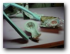
The
battery is taped to the inside base of the neck. I used heat shrink
tubing to attach the LEDs to the posts, and soldered all the connection
together.
On the other side of the face, I wanted a defined skeletal
appearance, and created a stencil of a skull outline, pinned it in
place and then gently dry brushed black paint creating the skull
features. After this dried, I used some RIT whitener in solution,
and highlighted some of the features, particularly around the
eyes. The UV LEDs illuminate this gently, and other black lights
around the yard occassionally make the RIT glow in other spots on
the figure as it glides by them.
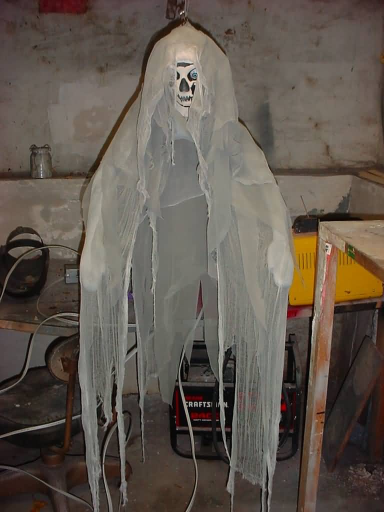
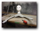
Once the face
was painted, I draped on cheesecloth and nu-see-um scrim, in
alternating layers (to add a little body), and used a razor to cut
the material up yielding a nice ragged feeling. Afterwards, used
grey spray paint to dirty the finish, which also stiffened the
fabrics some, and got the materials to curl and rope up a bit, a
nice effect I think.
I had been inspired by Circe Du Soleils Quidam show, and wanted a
very grey, very dark, slow moving ghost. |