![]()
|
click on images to see full size
|
|||
|
All
information presented Your
use of this information |
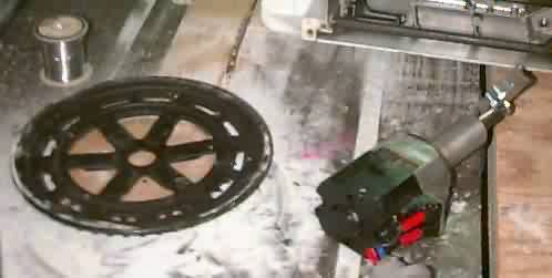
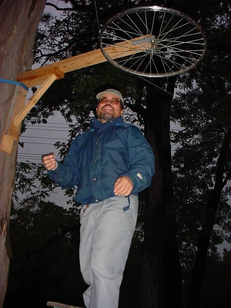
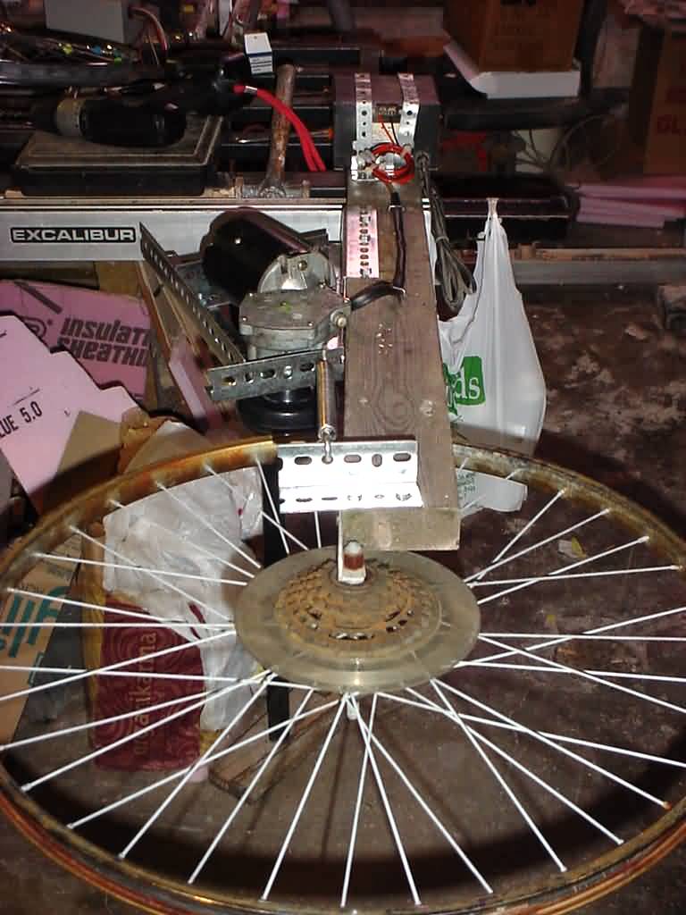
Well after a few weeks of racing the trash man to the stash, I came up with enough wheels to start building this prop. First I stripped
the wheels from the bike saving the largest for the prop. The
idea struck be to use the existing crank gears, chain and sprocket
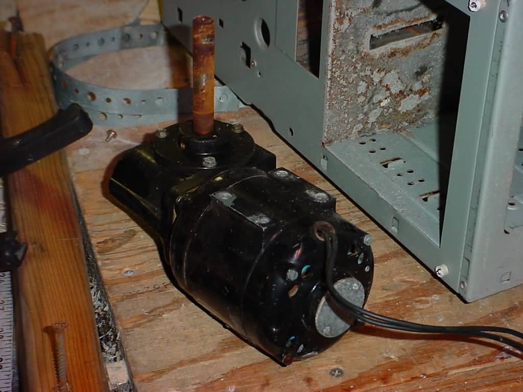
from the ten speed to act as the drive transmission. I also gutted
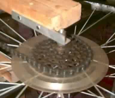
a defunct sewing machine for the motor. Next came cutting out two discs of acrylic to sandwich the crank gears. Thru one disc I drilled three arrayed holes, thru the other I made three more holes plus two more holes to use to mount the angle stock motor connector with. Making sure that the holes left the motor shaft centered on the disc. This was all assembled with 1/4-20 x 1.25" bolts and lock nuts sandwiching the crank gear and 1/4-20 x 3/4" bolts and lock nuts between them. The motor connector was attached to the shorter bolts. Next I drilled
a pocket about 1/2" deep with a 1-1/8" forstner bit see image below
to get the idea. On testing it,
the thing rocked! Perfect speed, but the crank was a hair off
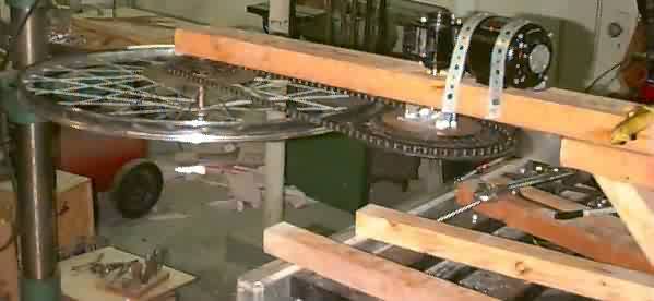
centre. I will scavange a derailuer this year and add that to
get tensioned slack. In theory I would be able to adjust the speeds
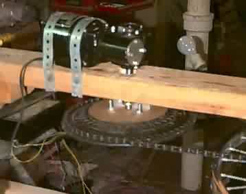
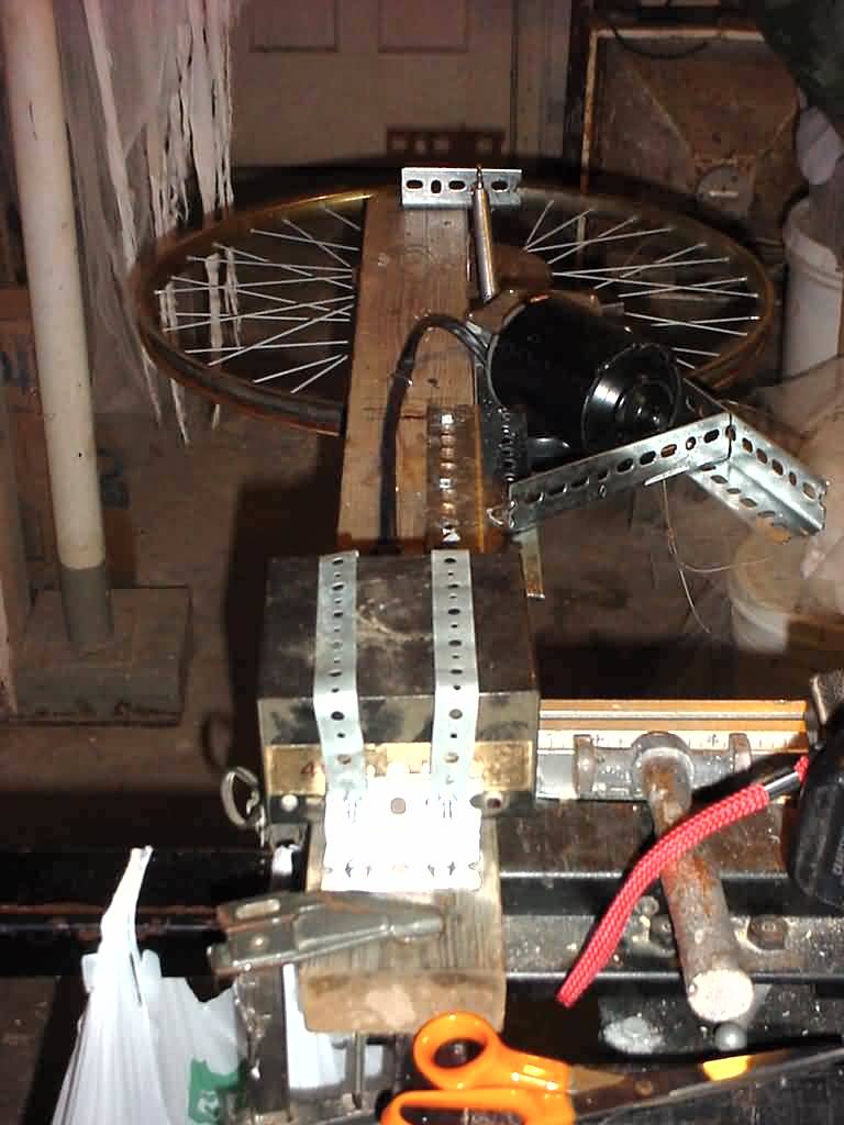
as well. hehehe. To install them,
we used 4 - 5" x 1/4" lag screws per bracket. To get them
all level to each other we used a laser pointer and a level pointing
from the top of the first mounting assembly, once leveled, to
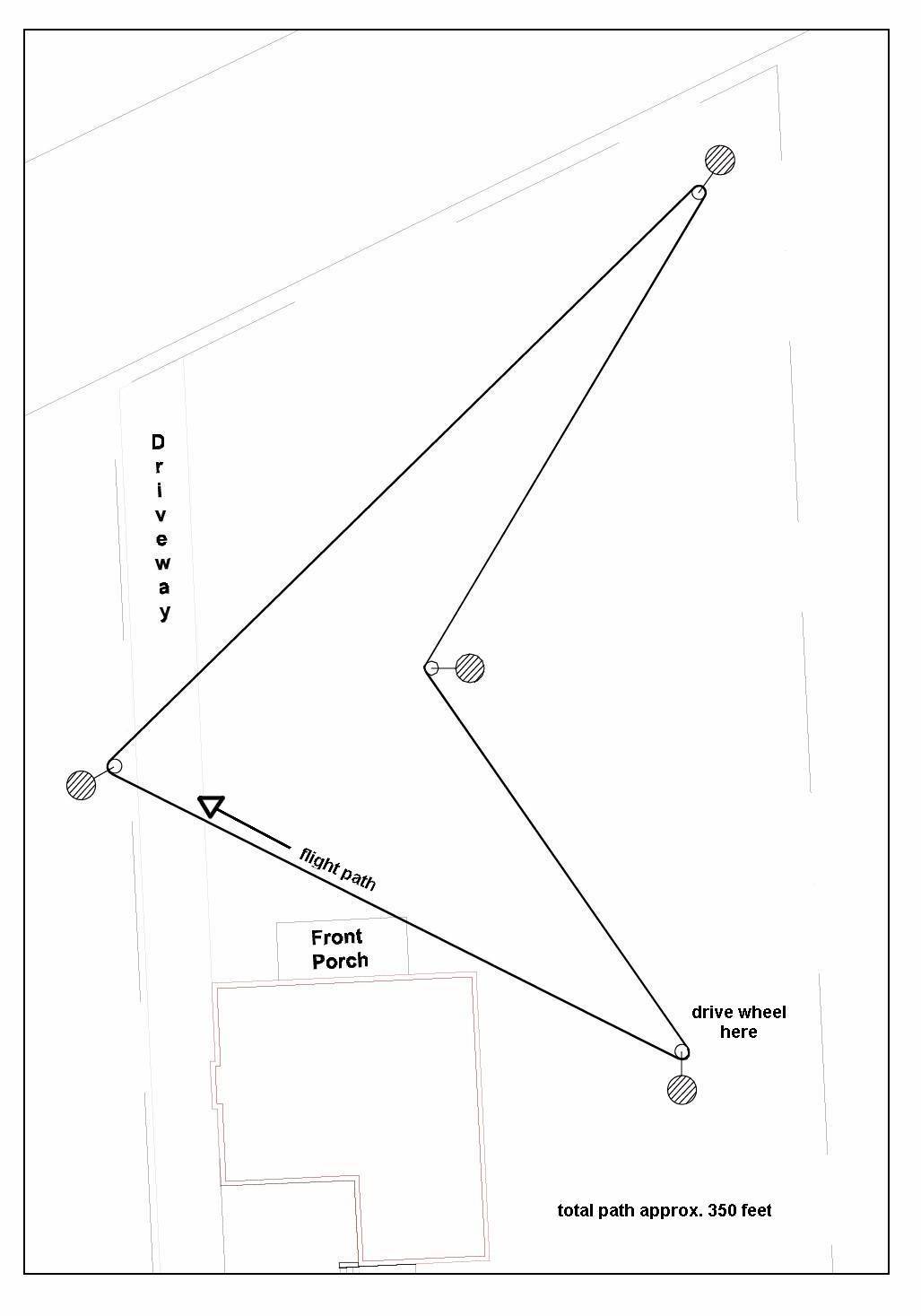
the next tree the the dummy wheel(s) would be mounted to. Its very elastic and strong. It helps to have a few ladders and friends to put the line up. As you hook the line to each wheel, tape it in place as a temporary measure, until you come to tie the ends together. To connect it we used a bowline knot for one end. The Bowline Knot is one of the most used loop knots. This variant is most used in the world. Probably due to its simplicity, security, and its relationship with the Sheet bend. Keep the cross point in step A between a finger and thumb and make a clock-wise turn with your wrist. Without the loop in between, it is the same knot. If the loop is expected to be heavily loaded, the bowline is, in fact, not secure enough. There is a rule of thumb which states that the loose end should be as long as 12 times the circumference for the sake of safety.
The Bowline: "Lay the bight to make a hole. Then under the back and around the pole. Over the top and thru the eye. Cinch it tight and let it lie" To tension it we used a tautline hitch for the other end.
|
It was rather amazing how much tension we could apply to this to get it taut. Once the line was taut, remove the tape. We attached the ghost at the loop of the bowline. Basically the ghost was a foam ball six inches in diameter, with a hanger attached beneath it. Then it was layered with tuelle and gauze. Weighed perhaps three pounds. The ghost will be different soon, made from a wig form - so it has a distinct head on it. The head will have blue led eyes powered by a nine volt, plus arms reaching out ahead of it. This means it will need two mount points, ideally we want more ghosts in the loop. The masons line seems capable of taking the additional weight. One of the nice things about the setup, is that it can easily be made to run past other props and take advantage of the lighting associated with them. It looked great whizzing by the ghost ring, the FCG and the porch, which were all illuminated with black lights. The cabling might change, we have a tarred netting line, supposedly minimal stretch, and we have 1/16th" steel cable. Just gonna have to experiment during the off season in the garage. Since I scavenged so many bicycles this year, and the potential to aquire more, we will be at least extending the loop with additional wheels, or adding a second run. There
have been some changes with the drive assembly, Halloween 2002,
the motor crapped out 15 minutes before Halloween. I
had other gear motors, but nothing with a drive shaft like the
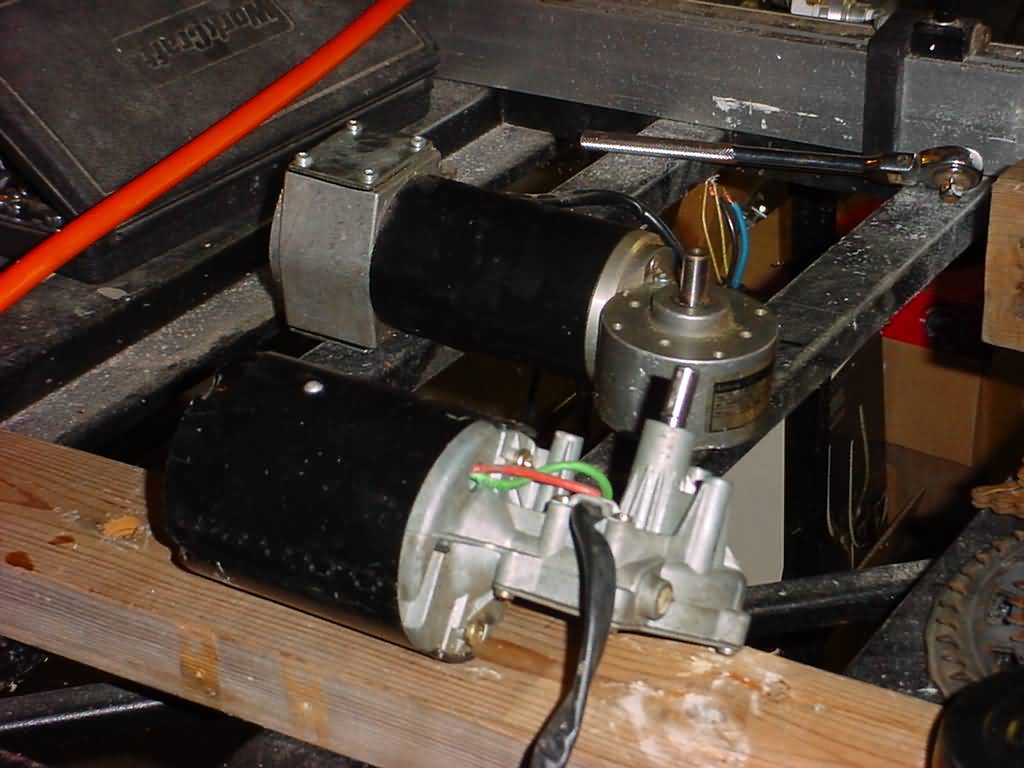
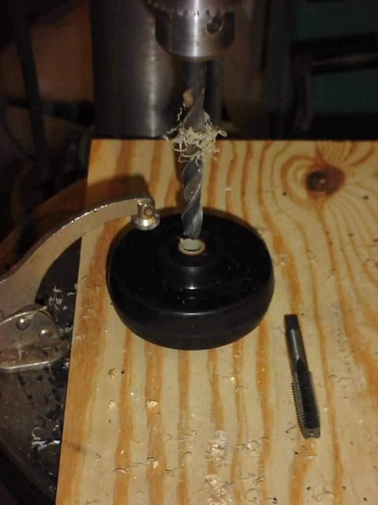
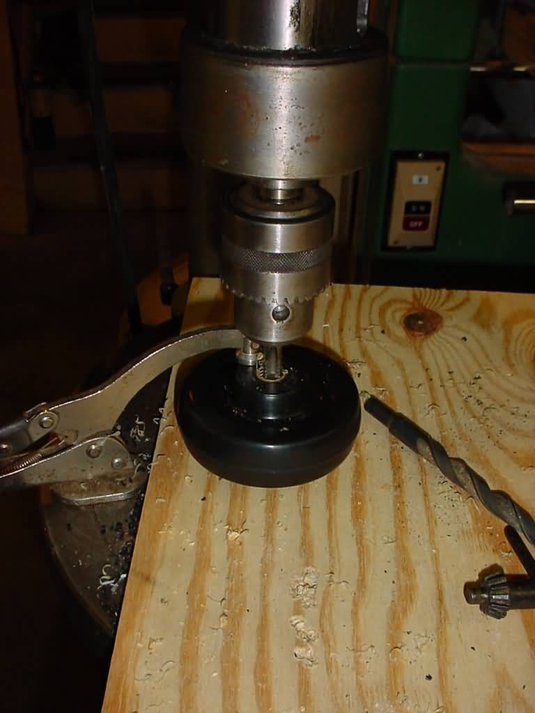
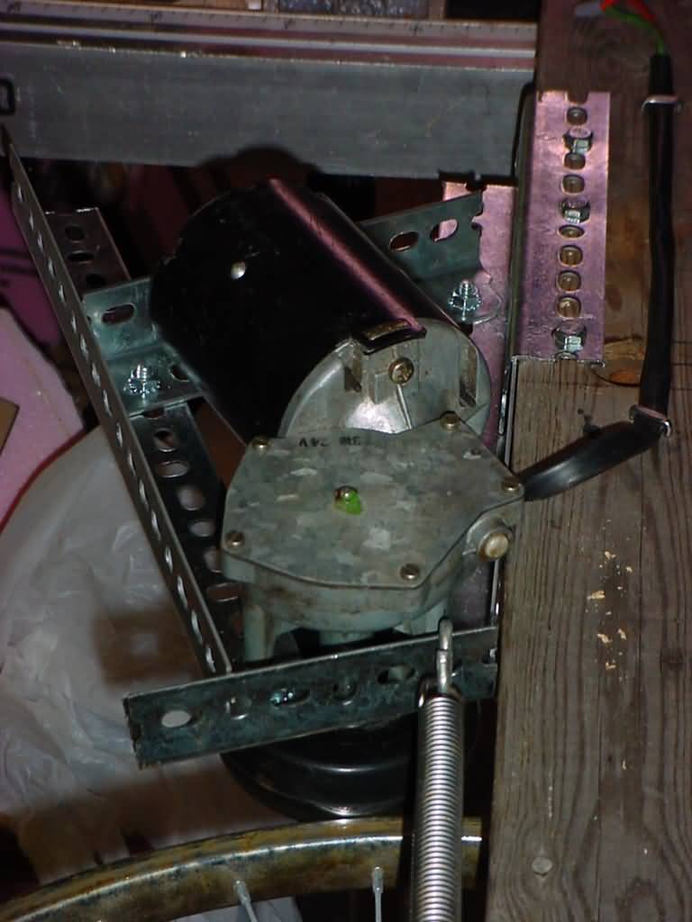
previous one, so it was time to rethink the connection. My dancing ghost ring is being set up with a drive motor with a tension traction drive (using a caster wheel) so why not here? Its
necessary to drill and tap the caster wheel (removed from the
assembly of course) to fit the shaft, and a threaded insert (to
act as a stop inside the the caster axle hole) Once
tapped, the caster is test fit onto the motor shaft, drilled perpendicular
to the shaft, removed, threaded, to fit a hex head retainer screw,
and reassembled. This hold the whole thing together, and prevents
any slippage on the shaft. From
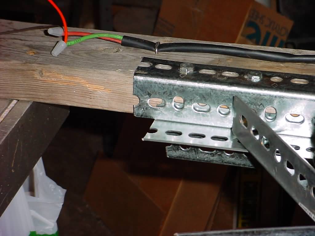
here, its time to build a mount rig for the motor. Piecing
together some galvanized "L" bracket and bolting it all
together and then bolting the motor to the carriage the motor has
a place to sit. One thing I have noticed previously (ghost ring
build) is that a tensioner is really helpful in maintaining
consistent contact of the drive wheel (caster) to the bicycle
wheel. To facilitate this a few pieces of "L" were cut,
2 bolted together back to back then bolted to the bottom of the
2x4 with the flat face upwards for the carriage to slide on. A
third bolted to the 2x4 to make a slide slot, leaving about an
1/8" gap between the 2x4 side and the "L". A
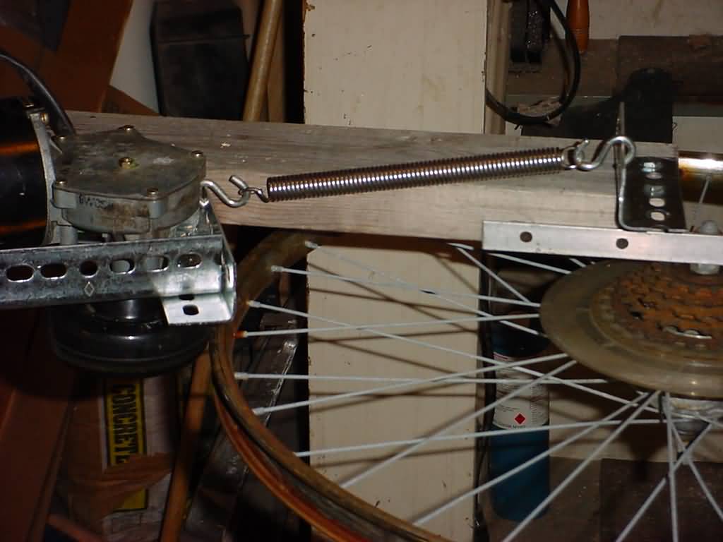
tensioner was added using a screen door spring, and another piece
of "L" bolted to the top end of the 2x4. The spring was
connected using "S" hooks. A
power supply was mounted to the other end of the 2x4 mount, wired
up to the motor and tested for continuity. More to come when it warms up a bit and I re-install the drive line (now 1/16" steel cable). |
|
|
More
pics when I get em from friends who helped with the haunt. |
|||
|
You
are visitor # |
|||